The second core principle of Cisco SD-WAN security is that security functions are built directly into WAN edge routers. To understand why this is important, imagine a traditional branch with multiple separate hardware security devices. Now imagine that each device is paired with a redundant one for high availability. In the end, a traditional branch might have two firewalls, two IPS devices, two Proxies, two URLF/AMP devices, and so on. This creates what we call network sprawl. Instead of managing one integrated platform, the IT team must deploy, monitor, patch, and troubleshoot a whole stack of security devices at every location.
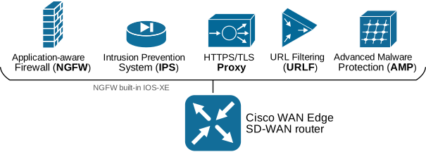
Cisco SD-WAN adopts a more modern approach. They realized that networking and security are no longer separate. So, every SD-WAN router includes integrated next-generation firewall (NGFW), application awareness, Intrusion Prevention (IPS), URL filtering, Advanced Malware Protection (AMP), Segmentation, Cloud security, and Zero Trust Enforcement, as shown below.
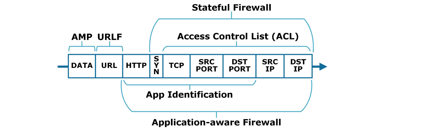
The following diagram shows what part of a network packet is inspected by every security feature available in the WAN edge routers’ firmware.
The benefit of the integrated security model is lower TCO (Total Cost of Ownership) because security is much closer to the edge, where traffic first enters and leaves the site.
Enterprise Firewall with Application-awareness
Nowadays, security is the topmost priority of every organization. Firewalling is one of the basic yet essential forms of network security that organizations rely on. Over the years, firewalling functionality was performed by separate hardware appliances (FWs) that sit behind WAN edge routers. This contributed to the network sprawl.
Cisco has integrated an Application-aware Enterprise Firewall directly into the firmware of Edge routers, eliminating the need for separate firewall appliances at remote sites. The firewall is represented as a localized security policy (NGFW policy), which brings all the benefits that the policy framework provides. It allows security teams to add and edit firewall rules applied to hundreds of sites at the same time through vManage's GUI.
What is Zone-based FW architecture?
To understand the Cisco SD-WAN firewall, you must first understand zones. In the past, stateful firewalls used the Context-Based Access Control (CBAC) architecture, where individual interfaces were configured with a stateful inspection policy. This architecture introduces many inefficiencies, such as:
- Interfaces often change over time, but the security intent usually does not. However, an interface change requires a change in the firewall policy.
- In conflict with high-availability techniques such as ECMP and Active-Active forwarding.
- Does not scale efficiently because interface numbering differs between models, which prevents you from applying the policy at scale. However, VPNs are typically consistent across the network edge.
The zone-based firewall architecture (ZBFW) overcomes these inefficiencies by using zones instead of interfaces and applying inspection policies to traffic between zones rather than between individual interfaces. Zones abstract the router's interfaces away from the security inspection policies. You can add and remove interfaces from zones without changing the inspection policy. The ZBFW architecture is much more flexible, has a hierarchical structure, and scales more efficiently than the old CBAC architecture.
Types of Zones
A zone is a logical abstraction that represents multiple router interfaces. Since SD-WAN utilizes the concept of VPNs and each interface on an edge router is ALWAYS assigned to a VPN/VRF, a zone is a logical group of one or more VPNs. However, in the end, a zone translates to a group of interfaces. For example, if we define a zone named "Employees," that includes VPNs 3 and 4, all router interfaces that are assigned with VPN ids 3 and 4 will be part of that zone.
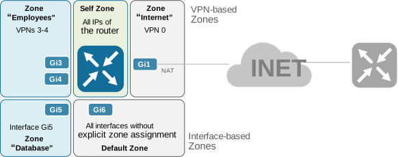
There are a few different types of zones, depending on whether the zone is user-defined or system-defined or how it is configured. Figure 11.11 shows an example of each zone type.
VPN-based Zones
The most general type of zone is a VPN-based zone, which groups one or more VPNs. The output below shows how we define a VPN-based zone.
zone security EMPLOYEES
vpn 3-4
!
zone security ENGINEERING
vpn 9
!
Since the VPN ID is a globally significant value for the SD-WAN domain, a zone defined by a grouping of VPNs could be reused in multiple firewall policies, which makes it very scalable. Notice that a particular VPN ID can be part of only one zone.
Interface-based Zones
Another way to define a zone is by assigning individual interfaces. This allows for greater granularity for the firewall policy configuration. For example, different interfaces part of the same VPN segment can be assigned to different zones (hence applying different firewall policies).
In most SD-WAN designs, though, VPN-based zones are still the natural starting point because they align with the segmentation model of the overlay fabric.
zone security DATABASE
!
interface GigabitEthernet5
  vrf forwarding 5
  ip address 10.3.5.1 255.255.255.0
  zone-member security DATABASE
 !
Notice that the same interface can be assigned to an interface-based and a VPN-based zone. Additionally, we can pair a VPN-based zone with an interface-based zone and vice versa.
Self-Zone
The self-zone is a system-defined zone that includes all routers' IP addresses. You do not create this zone manually. It is already there and can be used in a zone pair when you want to control traffic to or from the router.
zone security selfAll traffic to and from the self-zone is allowed by default. The solution allows you to apply a firewall policy to the traffic between the self-zone and another security zone.
However, you must be very careful with the self-zone. Restrictive policies between the self-zone and VPN 0 can affect SD-WAN control traffic, including DTLS or TLS control connections, BFD, and IPsec overlay traffic.
Zone Pairs
A zone establishes the security boundary where traffic is subject to firewall inspection. By default, if no firewall policy is explicitly applied between zones, all traffic within a zone is allowed, while all traffic between zones is dropped.
By default, Cisco SD-WAN blocks traffic between zones unless a zone-pair policy allows it. That default-deny behavior is one of the reasons zone-based firewalling is so effective. It forces you to be explicit about what traffic is allowed to cross a security boundary.
A zone pair is a logical association between two zones - one being a source zone and the other being a destination zone. A firewall policy is always applied to a zone pair and acts upon the traffic in the direction from the source toward the destination zone.
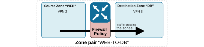
The configuration representation of the zone-pairing is as shown in the output below:
zone-pair security WEB-TO-DB source WEB destination DB
service-policy type inspect FIREWALL-POLICY
It is important to notice that the zone pair is a unidirectional association between two zones. Hence, when a firewall policy is applied to the zone, only the traffic crossing the zones from source to destination is subject to the firewall policy. This is a key idea. A policy from WEB to DB does not automatically create the same policy from DB to WEB. Firewall direction always matters.
Firewall Actions
When a firewall policy is applied to a zone pair, the traffic flows crossing the source zone are subject to the following three firewall actions:
- Inspect: The "inspect" firewall action provides stateful traffic control. The router creates connections for the matching flows and tracks their state. Subsequently, the router automatically allows returning traffic from the destination zone to the source zone in response to connection requests. Additionally, a parameter map can be applied to record connections' start/stop times, duration, data volume, etc.
- Pass: The "pass" firewall action provides stateless traffic control. The router simply forwards the matching traffic from the source to the destination zone. It does not track the state of connections. Returning traffic isn't allowed, so a parallel firewall policy must be configured and applied for the traffic in the opposite direction. This firewall action is typically used with protocols such as ISAKMP, IPsec, and DTLS/TLS, which have predictable behavior and are inherently secure.
- Drop: The "drop" firewall action silently discards the matched traffic. Silently means that the router does not notify the relevant end host. (when an ACL drops traffic, the router sends an ICMP host unreachable message to the relevant end-host).
Firewall Rules Match Criteria
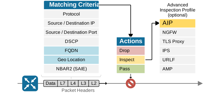
The Cisco Catalyst SD-WAN enterprise firewall can match traffic on more than just IP addresses and ports. Like other SD-WAN policy types, it supports common fields such as source and destination prefixes, ports, and protocols. But the enterprise firewall adds two very useful options that control and data policies do not provide: FQDN-based matching and geolocation-based matching (highlighted in blue). These features make firewall rules easier to scale and easier to read, especially in large enterprise environments.
FQDN Lists
The FQDN lists are a powerful new tool that Enterprise Firewall introduced in order to solve the following challenges:
- Configuring firewall rules for hosts with dynamically changing IP addresses is unscalable.
- Configuring firewall policies with fixed IP is cumbersome and leads to a large number of rules.
FQDN-based rules let the firewall match traffic by domain name instead of relying only on fixed IP addresses. This is helpful when a server changes its IP address over time, or when using names is simply easier than maintaining long IP-based rule sets.
However, keep in mind that this feature is mainly intended for matching standalone servers in a data center or private cloud, not for general Internet websites. Public web services often use redirects, CDNs, and many related hostnames, which can make matching unpredictable.
FQDN-based rules work in two steps:
- Step 1 – DNS Resolution
- The router snoops DNS response packets and stores the FQDN to IP mapping into the DNS snooping agent (DSA) database.
- If a DNS response has a higher TTL value than the one in the DSA database, the database is updated.
- Step 2 - Policy Lookup
- Without step 1, policy lookup based on FQDN can’t occur.
- For an incoming flow, an IP-to-FQDN lookup happens first.
- If a flow is successfully matched based on the DSA database using FQDN, the corresponding firewall action is taken.
When you design firewall rules based on FQDN lists, keep in mind the following design considerations:
- The feature is designed for matching enterprise servers/clients using FQDN names and not for matching traffic to public websites (for that purpose, we have app lists and the URLF policy). The reason is that websites use CDNs with different domain names that may be matched incorrectly.
- Multiple FQDN names resolving to the same IP address may result in unpredictable results (hence not recommended).
- For the feature to work in dual-homed topologies, the router must be able to snoop DNS query/response packets. Therefore, the feature may not work when DNS is encrypted, such as with DNSoverHTTPS (DoH) or DNSoverTLS (DoT).
Geolocation Lists
Another useful match option is geolocation. With geolocation-based rules, the enterprise firewall can allow, inspect, or block traffic based on the country or continent associated with an IP address. This gives administrators a simple way to limit access to or from specific parts of the world without building large prefix lists by hand.
The geo-location list can be used as a source or destination matching criterion for traffic. Geographical information is part of the IOS-XE image and includes IP-to-geo-location mapping of countries and continents. However, notice that at the time of writing, the SD-WAN manager doesn’t support automatic Geo-Information Database updates. Therefore, a manual process is used if an update to the Geo database is required (documented in Cisco’s official configuration guide).
In practice, these two features make the enterprise firewall much more flexible. They extend the NGFW policy beyond basic IP and port filtering and make it much closer to the way enterprises actually think about their traffic.
Firewall Scenario Use Cases
Inter-zone Firewall
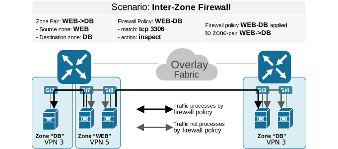
The most common use case of the NGFW is to protect traffic that moves between different zones (e.g., between VPNs). This is called inter-zone firewalling. A pair binds a source zone to a destination zone and applies a firewall policy with rules to the traffic flowing between them, as shown in the diagram below.
Recall that VPN segments are global. Within the same VPN, full IP reachability exists by default unless you change it with a topology policy or a VPN membership policy. Different VPNs, however, are isolated from each other by default at the routing layer. In other words, a router doesn’t have OMP routes for VPN5 in its VPN3 routing table and vice-versa. For traffic to pass between different VPNs, routing between those VPNs must exist first. One common method to provide routing between VPNs is to configure route leaking on vSmart with the export-to action (as we did in lab#7.7). In newer releases, route leaking can also be done directly on edge routers.
Also, notice that zone pairs are directional. A zone pair defines traffic flow only from the source zone to the destination zone (see the arrows). If you want traffic to be inspected in both directions, you must create two separate zone pairs and apply a policy for each direction.
Inter-zone firewalling is useful when you want to allow only specific traffic between separate VPN segments. Route leaking gives the VPNs IP reachability, but it does not control the traffic in a granular way. For example, in Lab 7.7, we configured route leaking between VPN 3 and VPN 5 and between VPN 4 and VPN 5. As a result, networks in those VPNs can now reach each other at Layer 3. For instance, hosts in VPN 3 (10.3.3.0/24) can reach hosts in VPN 5 (10.1.5.0/24).
However, simple reachability is often not enough. In many designs, you do not want to allow full any-to-any communication between the two VPNs. Instead, you may want to permit only certain hosts, applications, or port numbers. This is where an inter-zone firewall policy becomes necessary. It lets you keep the routing path between the VPNs, while still enforcing precise security rules on the traffic that is allowed to cross from one zone to another.
Intra-zone Firewall
You can use the Enterprise Firewall to inspect traffic not only between different zones, but also within the same zone (e.g. within the same VPN). This is called intra-zone firewalling. In practical terms, it means you can apply a zone pair in which the source and destination are the same user-defined zone, such as VPN 3 to VPN 3. Then, you apply firewall rules on traffic between users that belong to that same VPN, as shown in the diagram below.
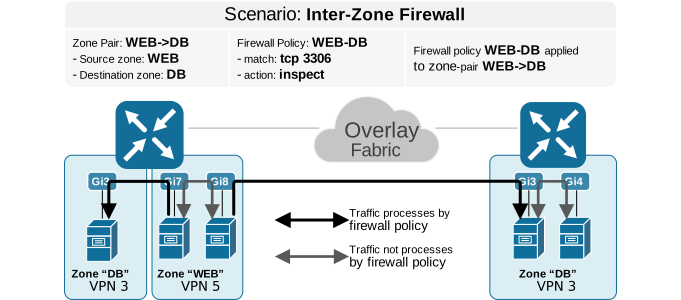
This design is useful when you want to limit east-west traffic and reduce the spread of internal threats inside a VPN segment. For example, hosts in the same user VPN may still need to be filtered based on IP prefixes, ports, protocols, or applications.
Keep in mind that the traffic must actually enter and leave the edge router for the firewall policy to have an effect. If two hosts communicate through a downstream Layer 3 switch and the flow never passes through the router, the NGFW policy does not see that traffic and cannot inspect it.
DIA/DCA Firewall
A DIA/DCA firewall policy is used to protect local users as they access Internet-based services directly from the branch. In this design, traffic enters the WAN Edge router from a service-side VPN, such as a user or server segment, and then exits the router toward the Internet through a transport interface in VPN 0. This means the firewall rule is meaningful only when the traffic actually passes through the router in both directions, which is normally the case in a dual-home site with direct Internet access.
For this reason, in a DIA or DCA firewall zone-pair, the destination zone is typically mapped to transport VPN 0. VPN 0 represents the underlying transport network and provides the path toward the public Internet. The source zone, on the other hand, represents the internal LAN-side segment that is initiating the connection. This allows the Cisco SD-WAN firewall to inspect and control outbound Internet traffic at the branch WAN Edge, without requiring the traffic to be backhauled first to a central data center.
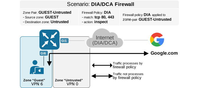
The diagram above shows this DIA/DCA security model in action. Hosts in the source zone send traffic toward the Internet, and the WAN Edge applies the firewall policy as the traffic moves from the service-side VPN to VPN 0.
In this way, the router can enforce security rules on locally broken-out Internet traffic while still preserving the simplicity and centralized policy model of Cisco SD-WAN.
Firewall Key Takeaways
- FQDN lists can be configured as source/destination matching criteria in a firewall policy. FQDN-based rules work in two steps:
- Step 1 - DNS Resolution
- The router snoops DNS response packets and stores the FQDN-to-IP mapping into the DNS snooping agent (DSA) database.
- If a DNS response has a higher TTL value than the one in the DSA database, the database is updated.
- Step 2 - Policy Lookup
- Without step 1, policy lookup based on FQDN can’t occur.
- For an incoming flow, an IP-to-FQDN lookup happens first.
- If a flow is successfully matched based on the DSA database using FQDN, the corresponding firewall action is taken.
- Step 1 - DNS Resolution
- Application lists can also be configured as source/destination matching criteria in a firewall policy. They also work in two steps:
- Step 1 - L3/L4 match
- Traffic matching based on L3/L4 object groups and session is created with Inspect Action.
- Step 2 - L7 App detection Lookup
- For specific apps to be dropped, a firewall rule must include an “inspect” action to match L3/L4 fields first before it can act on the app-list.
- Step 1 - L3/L4 match
- Rule Sets
- Grouping of multiple rules (5 tuples) which share the common action (inspect/pass/drop).
- Rulesets can be shared across multiple sub-policies (for a zone-pair) in a security policy or across security policies
- Geo Location lists
- Geo Location can be used as source/destination prefix lists.
- Geoinformation includes mapping of IP addresses of countries and/or continents.
- High-speed Logging (HSL)
- o Firewall logs are saved for troubleshooting purposes without impacting performance.
- o Firewall logs can be exported in NetFlow v9 format to an external log collector such as SIEM.
- o Notice that HSL and system logging are mutually exclusive.
- IPv6 is supported but with some limitations. For example, FQDN and Geo Location matching only works for IPv4 (as of time of writing). Newer releases continually add support for IPv6.