The first real deployment step in setting up an SD-WAN home lab is to deploy and onboard the SD-WAN controllers. The process involves multiple steps, which this lesson covers in detail below.
Physical Topology
First, let's say that, for all hands-on examples in this book, I used the EVE-NG Community Edition on a virtual machine hosted on Microsoft Hyper-V on Windows 11. In this lesson, I explain why I use Hyper-V and how you can set up a similar environment. However, you can run both EVE-NG and CML on ESXi, VMware Player, VMware Fusion, VMware Workstation, or any other hypervisor at your disposal. That's the advantage of EVE-NG/CML being packaged as a virtual machine.
The physical topology used throughout the book is shown in the diagram below. You can re-create it on EVE-NG/CML or download the EVE-NG or CML file from the download section at the end of the chapter. If you want to copy/paste some of the configs, make sure you use the same interfaces when re-creating or modifying the topology.
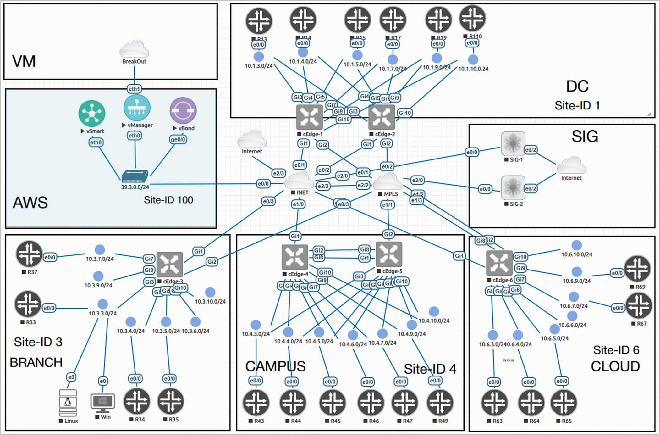
In this part of the chapter, we will work only with the SD-WAN controllers. We will focus on the edge routers' onboarding and configuration in the next part of the chapter.
Get the Software Images
To deploy the Cisco Catalyst SD-WAN controllers, of course, you first need to download the software images. Here you typically have two options:
Option 1: Download the images from Cisco.com
The first option is to download the controller images directly from Cisco.com. In this case, you need a Smart Account (SA) with the proper download entitlement. If you work for an organization that already uses Cisco equipment, the easiest approach is usually to ask the Smart Account administrators to download the images for you.
An important detail is to download the correct ones for your specific deployment. If you are going to use EVE-NG, CML, GNS3, or other similar KVM-based lab environments, you need to download the KVM controller images with the extension .qcow2.
For example, for this demonstration, we are going to use the following controller images:
- Cisco Catalyst SD-WAN Manager: viptela-vmanage-26.1.1.1-genericx86-64.qcow2
- Cisco Catalyst SD-WAN Controller: viptela-smart-26.1.1.1-genericx86-64.qcow2
- Cisco Catalyst SD-WAN Validator: viptela-bond-26.1.1.1-genericx86-64.qcow2
However, if you deploy the controllers directly on ESXi, you must download the OVA images with the extension .ova.
Option 2: Use Cisco CML as a virtual environment
If you do not have access to a corporate Smart Account, the easiest option is to use Cisco Modeling Labs (CML). Cisco CML provides the Catalyst SD-WAN images built-in (through the supplemental ISO). This means you can build an SD-WAN lab without having to search for each controller image separately. This makes CML especially useful for students and engineers who don't have access to a corporate SA account.
The only real downside of Cisco CML is that it is a paid product. At the time of writing, a personal CML license for 20 nodes costs around US$199 per year. However, Cisco regularly offers discounts, sometimes up to 50%, which means you may be able to purchase it for around US$100.
Transfer the Images to EVE-NG
Once you have the images and the virtual environment powered up, you must create a folder for each at /opt/unetlab/addons/qemu and transfer each image into its respective folder using FileZilla, WinSCP, or another similar tool, as shown in the screenshot below.
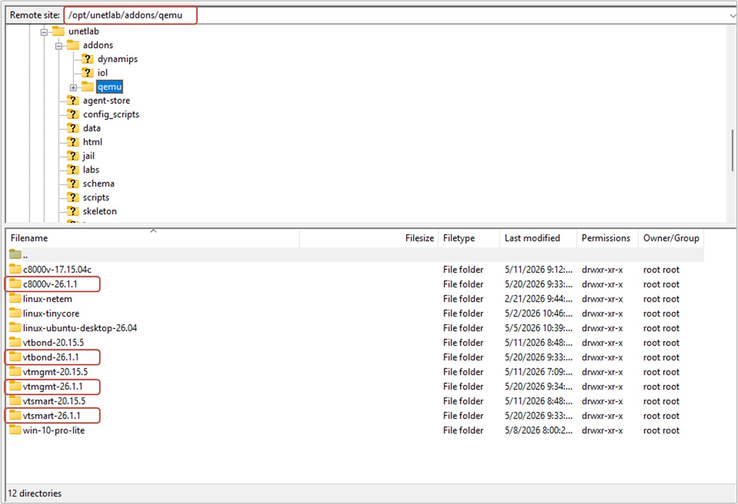
You can also create the folders via the CLI, as shown in the output below.
##  Creating Folders
mkdir /opt/unetlab/addons/qemu/vtbond-26.1.1
mkdir /opt/unetlab/addons/qemu/vtsmart-26.1.1
mkdir /opt/unetlab/addons/qemu/vtmgmt-26.1.1
After uploading the images to their respective folders in the VM, you must rename the original files to virtioa. Additionally, you need to create an additional virtual disk for the vManage controller, as shown highlighted in green:
## vManage
cd /opt/unetlab/addons/qemu/vtmgmt-26.1.1
mv viptela-vmanage-26.1.1-genericx86-64.qcow2 virtioa.qcow2
/opt/qemu/bin/qemu-img create -f qcow2 virtiob.qcow2 150G

## vSmart
cd /opt/unetlab/addons/qemu/vtsmart-26.1.1
mv viptela-smart-26.1.1-genericx86-64.qcow2 virtioa.qcow2

## vBond
cd /opt/unetlab/addons/qemu/vtbond-26.1.1
mv viptela-edge-26.1.1-genericx86-64.qcow2 virtioa.qcow2

## Fix permissions
/opt/unetlab/wrappers/unl_wrapper -a fixpermissions
Set up the nodes
Once you have uploaded the controller images and renamed the files, you need to allocate sufficient resources to each controller node. Make sure to assign at least 4 vCPUs and 48GB of RAM to the vManage controller, or it may not start at all.
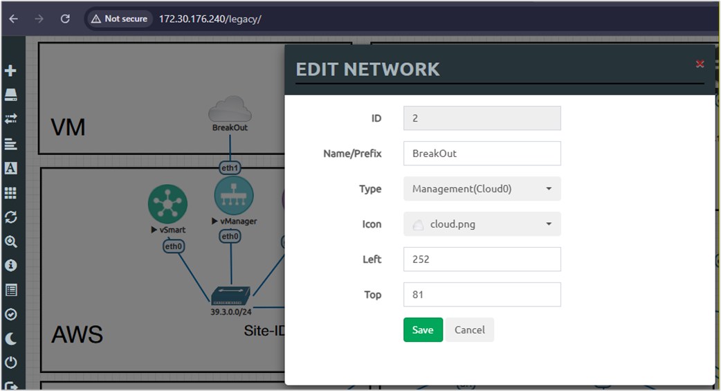
Additionally, note that the vManage controller's eth1 interface is connected to a cloud network named BreakOut. This is the Management network of the EVE-NG VM, which connects to the host via the vnet virtual network adapter. This interface is used to access the controller's GUI via the PC you work on.
Additionally, do not forget to enable the Intel VT-x or AMD-V option in the virtual machine and add a secondary NIC.
Controllers Bootstrap Configuration
Now it is time to power up the controller nodes and log in via the console. Default credentials for all controllers are admin/admin. When vManage boots for the first time, it will ask which storage device to install the software on. Please make sure to use the virtual disk you have created in the previous step.
Sun Jun 14 08:15:29 UTC 2026: System Ready
viptela 26.1.0 vmanage /dev/ttyS0

vmanage login: admin
Password: admin

Welcome to Viptela CLI
admin connected from 127.0.0.1 using console on vmanage
You must set an initial admin password different from default password.
Password:
Re-enter password:

1) COMPUTE_AND_DATA
2) DATA
3) COMPUTE
Select persona for vManage [1,2 or 3]: 1
You chose persona COMPUTE_AND_DATA (1)
Are you sure? [y/n] y

Available storage devices:
vdb     150GB
sr0     0GB
1) vdb
2) sr0
Select storage device to use: 1
Would you like to format vdb? (y/n): y
Once all devices boot up, it is time to enable basic connectivity between the Cisco SD-WAN controllers. The following bootstrap configurations are the minimum required to achieve basic connectivity between controllers, as per our physical lab topology.
!vBond
system
 host-name vBond
 system-ip 1.1.1.10
 site-id 100
 organization-name networkacademy-io
 vbond 39.3.0.10 local
!
 interface ge0/0
  ip address 39.3.0.10/24
  tunnel-interface
   encapsulation ipsec
   allow-service all
  !
  no shutdown
 !
 ip route 0.0.0.0/0 39.3.0.254
!
!vManage
system
host-name vManage
system-ip 1.1.1.20
site-id 100
organization-name networkacademy-io
vbond 39.3.0.10
!
vpn 0
interface eth0
ip address 39.3.0.20/24
!
no shutdown
!
ip route 0.0.0.0/0 39.3.0.254
!
vpn 512
interface eth1
ip dhcp-client
no shutdown
!!vSmart
system
host-name vSmart
system-ip 1.1.1.30
site-id 100
organization-name networkacademy-io
vbond 39.3.0.10
!
vpn 0
interface eth0
ip address 39.3.0.30/24
!
no shutdown
!
ip route 0.0.0.0/0 39.3.0.254
!At this point, each controller must be able to ping any other in VPN0 successfully. If, for whatever reason, one of the devices is unreachable, you should not proceed; instead, troubleshoot and resolve the issue.
Certificates
At this point, controllers can ping each other, but they cannot establish connections because they do not trust each other! Controllers must establish a chain of trust to validate their identities. Each controller must have a root certificate and a controller certificate signed by a trusted Certification Authority (CA).
We will use the vBond controller as an Enterprise Root CA to create this lab environment. In essence, we will just create a new private key and a self-signed root certificate in vBond's Linux, and then install this root certificate in vManage. vManage will then install this root certificate on the other controllers, as shown in the diagram below.

vBond as a Root CA
Okay, we want the vBond validator to be the Root CA. The first step is to generate a Root CA private key, as shown in the CLI output below. Use vshell / viptela_cli to switch between Shell and CLI modes on vBond.
vBond# vshell
vBond:~$ openssl genrsa -out ROOTCA.key 2048
Generating RSA private key, 2048 bit long modulus
........+++..............................................+++
e is 65537 (0x10001)
Then we generate a ROOTCA.pem certificate and sign it with the private key we created. The ROOTCA.pem file contains the root certificate that we must install on all cEdge routers and SD-WAN controllers.
vBond:~$ openssl req -x509 -new -nodes -key ROOTCA.key -sha256 -days 1024 \
>     -subj "/C=US/ST=NY/L=NY/O=networkacademy-io/CN=networkacademy-io" \
>     -out ROOTCA.pem
vBond:~$ ls -l
total 12
-rw------- 1 admin admin 1704 Jun 14 09:33 ROOTCA.key
-rw------- 1 admin admin 1318 Jun 14 09:34 ROOTCA.pemNow you need to log in to the vManage GUI interface. This is done using a web browser and entering the URL https://[vManage-VPN512-IP-address]. However, to find the vManage IP address, you must check the IP assigned via DHCP to vManage's eth1 interface, which connects to the VM's management interface (named BreakOut), as shown below.
vManage# show int eth1
interface vpn 512 interface eth1 af-type ipv4
 ip-address      172.30.189.3/20
 if-admin-status Up
 if-oper-status  Up
 encap-type      null
 port-type       mgmt
 hwaddr          50:00:00:01:00:01
 speed-mbps      1000
 duplex          full
 uptime          0:00:12:59
 rx-packets      83
 tx-packets      87
Now, we log into vManage using the link https://172.30.189.3/.
Depending on the vmanage software version you use, you may end up on the Welcome admin landing page, which guides you through the initial settings the vManage controller requires, such as the organization name and vBond address. Alternatively, you can skip the initial wizard and go to Administration > Settings, and configure everything from there. You need to configure the following settings:
- Tenancy mode to Single Tenant.
- Set the Organization Name to be networkacademy-io.
- Set the vBond address to 39.3.0.10.
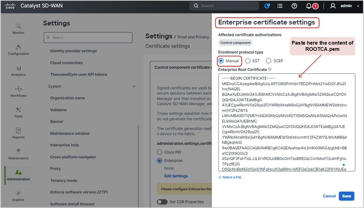
- Set the Controller Certificate Authorization to Enterprise. Then log in to the vBond shell, copy the content of ROOTCA.pem using cat ROOTCA.pem, and paste it into the Enterprise Root Certificate field, as shown in the screenshot below. Then you click Save.
Adding Controllers
Once we complete these steps, the vManage controller will have our root certificate. It is time to add the other SD-WAN controllers via the vManage GUI.
We go to Configuration > Devices > Control Components> Add Control Component and add the vBond and vSmart controllers. We enter the VPN0 IP address for each controller, along with the username and password.
At this point, the vManage controller installs the root certificate to each SD-WAN controller. Once completed, each controller must have our Enterprise root certificate. We should verify this using the show certificate root-ca-cert command, as shown in the output below.
vManage# show certificate root-ca-cert | in networkacademy
     Issuer: C=US, ST=NY, L=NY, O=networkacademy-io, CN= networkacademy-io
     Subject: C=US, ST=NY, L=NY, O=networkacademy-io, CN=networkacademy-io
vSmart# show certificate root-ca-cert | in networkacademy
Issuer: C=US, ST=NY, L=NY, O=networkacademy-io, CN=networkacademy-io
Subject: C=US, ST=NY, L=NY, O=networkacademy-io, CN=networkacademy-iovBond# show certificate root-ca-cert | in networkacademy
Issuer: C=US, ST=NY, L=NY, O=networkacademy-io, CN=networkacademy-io
Subject: C=US, ST=NY, L=NY, O=networkacademy-io, CN=networkacademy-ioIf a controller does not have our Enterprise root of trust, you should not continue ahead, but instead, troubleshoot the problem.
Controller Certificates
Now, before we continue with the next steps, let's quickly discuss what the different options are for acquiring certificates for the SD-WAN controllers.
Where do controllers get their certificates?
When it comes to controller certificates, there are a few different options you can use in a lab environment and in production as well. The most automated plug-and-play method is to sync your Smart Account / Virtual Account with the vManage controller and let it automatically handle everything for you, as shown at the top in the diagram below. In combination with Cisco hardware routers, which come with pre-installed identity certificates, this makes the entire process plug-and-play - no manual steps are required at all. This is the option that 90+ percent of the real-world deployments use, and you can see why in the diagram below.

On the other end of the spectrum is the option to use Enterprise PKI without any certificate enrollment protocols, such as EST and SCEP. In this option, all steps are executed manually by a network administrator, which, in practice, is very difficult to scale in large enterprise networks. However, for studying and hands-on labs, it is the best solution because it forces you to think about each step of the process and understand how everything fits together.
Look closely at the last option in the diagram above and think about it in the context of this hands-on example of controller deployment.
- We use vBond as an enterprise CA (we call it Root CA).
- Step 1. We have already done step 1. We generated an Enterprise root certificate (called ROOTCA.pem) and self-signed it with the Root CA private key (called ROOTCA.key).
- Step 2. We have already done step 2. We downloaded the Enterprise CA root certificate (called ROOTCA.pem) and installed it on the vManage controller.
- Step 3. vManage has already pushed the Enterprise CA root certificate to all other controllers (step 3).
Now, as you can see in the diagram above, it is time to generate a CSR for each controller, sign it with the Enterprise CA's private key (called ROOTCA.key), and upload the certificates to vManage so that the controller pushes them to all control components.
Let's start with the CSRs. We go to Configuration > Certificates> Control Components and generate a certificate signing request (CSR) for each one, as shown in the screenshot below.
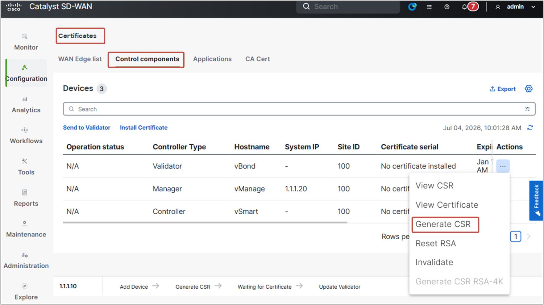
Ensure that each controller's operational status is “CSR Generated.” If that’s the case, we can go ahead and copy the CSR files to our Root CA (which is the vBond controller) and sign them.
The following output shows how to copy the CSR files to vBond.
vBond# vshell
vBond:~$ scp admin@39.3.0.30:/home/admin/vsmart_csr vSmart.csr
vBond:~$ scp admin@39.3.0.20:/home/admin/vmanage_csr vManage.csr
vBond:~$ scp admin@39.3.0.10:/home/admin/vbond_csr vBond.csr
vBond:~$ ls -alh | grep csr
-rw------- 1 admin admin 1.2K Dec 31 16:16 vBond.csr
-rw------- 1 admin admin 1.2K Dec 31 16:16 vManage.csr
-rw------- 1 admin admin 1.2K Dec 31 16:16 vSmart.csr
-rw-r--r-- 1 root root 1.2K Dec 31 15:27 vbond_csrNow that the CSR files are present, we sign them with the RootCA private key and generate a certificate for each controller, as shown in the output below.
vBond:~$ openssl x509 -req -in vBond.csr \
>     -CA ROOTCA.pem -CAkey ROOTCA.key -CAcreateserial \
>     -out vBond.crt -days 500 -sha256
Signature ok
vBond:~$ openssl x509 -req -in vSmart.csr \
> -CA ROOTCA.pem -CAkey ROOTCA.key -CAcreateserial \
> -out vSmart.crt -days 500 -sha256
Signature ok vBond:~$ openssl x509 -req -in vManage.csr \
> -CA ROOTCA.pem -CAkey ROOTCA.key -CAcreateserial \
> -out vManage.crt -days 500 -sha256
Signature okIn the end, we must have three certificates, as seen in the following output.
vBond:~$ ls -alh | grep crt
-rw-r--r--  1 admin admin  26K Dec 31 15:27 master_root.crt
-rw-------  1 admin admin 1.4K Dec 31 16:25 vBond.crt
-rw-------  1 admin admin 1.4K Dec 31 16:30 vManage.crt
-rw-------  1 admin admin 1.4K Dec 31 16:26 vSmart.crt
vBond:~$
It is time to install all controller certificates via the vManage GUI. Go to Configuration > Certificates > Controllers > Install Certificate.
Now that you have all certificates (.crt) in vBond's directory, you simply cat each of them and paste the output in the Install Certificate window as shown in the screenshot below.
For example, we take the value of vManage.crt as shown in the output below.
vBond:~$ cat vManage.crt
-----BEGIN CERTIFICATE-----
MIIDtzCCAp8CFECnnxKSiDGvEN88bclv/fsc/ajKMA0GCSqGSIb3DQEBCwUAMF8x
CzAJBgNVBAYTAlVTMQswCQYDVQQIDAJOWTELMAkGA1UEBwwCTlkxGjAYBgNVBAoM
EW5ldHdvcmthY2FkZW15LWlvMRowGAYDVQQDDBFuZXR3b3JrYWNhZGVteS1pbzAe
Fw0yMjEyMzExNjMwMzdaFw0yNDA1MTQxNjMwMzdaMIHQMQswCQYDVQQGEwJVUzET
MBEGA1UECBMKQ2FsaWZvcm5pYTERMA8GA1UEBxMIU2FuIEpvc2UxGjAYBgNVBAsT
ZAQ4EDJsOILeeW3/hWyXUUUrf2oWwkUtMiRSqxCSuBQm0DsifCKtPNlKzQ==
-----END CERTIFICATE-----
vBond:~$
And paste the value in the “Install Certificate” window.
If everything is good up to this point, the certificate should install successfully.
You repeat this for all controllers. In the end, when you go to Configuration > Certificates > Controllers, you should see that all controllers have Certificate Serial numbers. If that is the case, you click the Send-to-vBond function to propagate this information to vBond.
At this point, all controllers should be operational with valid certificates. Now it is time to bring up the tunnel interface on the vManage controller.
# on vManage
vpn 0
 interface eth0
  tunnel-interface
!
commit
Verification
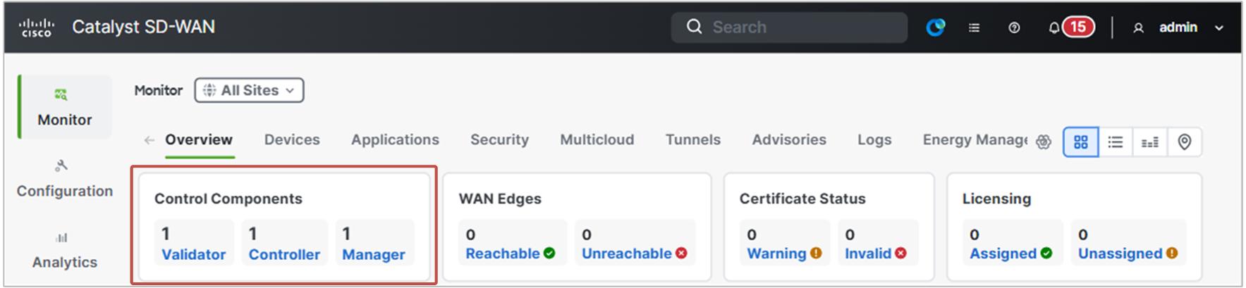
If everything has been successfully completed up to this point, each controller should have both root and device certificates installed, as well as a serial number. In the vManage GUI, you should see the controllers appear under the Control Components window, as shown below.
Additionally, as shown in the output below, each one must have established control connections to all other controllers.
vBond# show orchestrator connections | t

PEER     SITE            PUBLIC            SYSTEM    LOCAL
TYPE     ID   PUBLIC IP  PORT    PROTOCOL  IP        COLOR    STATE  UPTIME
-------------------------------------------------------------------------------
vsmart   100  39.1.1.30  12346   dtls      1.1.1.30  default  up     0:00:01:19
vsmart   100  39.1.1.30  12446   dtls      1.1.1.30  default  up     0:00:01:18
vmanage  100  39.1.1.20  12346   dtls      1.1.1.20  default  up     0:00:01:32
vmanage  100  39.1.1.20  12446   dtls      1.1.1.20  default  up     0:00:01:31
vmanage  100  39.1.1.20  12546   dtls      1.1.1.20  default  up     0:00:01:31
vmanage  100  39.1.1.20  12646   dtls      1.1.1.20  default  up     0:00:01:31
If everything is working up to this point, we can now go ahead and provision the Edge routers.