In our previous lab lesson for Centralized Policies, we restricted spokes of establishing data plane tunnels to other spokes by filtering out TLOC advertisements at the vSmart controllers. This allowed us to create a hub-and-spoke overlay topology of IPsec tunnels. However, after we finished with the topology manipulation, we didn't check whether there was actual IP reachability between the hub and the spokes and between the spokes themselves.
Let's look at our main topology for this lab series and check if any of the spokes (site-ids 60,70,80,90) has connectivity to the hub (site-id 50) or to other spokes.

We can verify if vEdge-4 (site 70) has all route entries in VPN1 by checking its routing table for that VPN. Obviously, it only knows about its own connected network and do not receive any routing information about the other sites.
vEdge-4# show ip route vpn 1
                                            PROTOCOL  NEXTHOP
VPN    PREFIX              PROTOCOL         SUB TYPE  IF NAME
-------------------------------------------------------------
1      172.16.70.0/24      connected        -         ge0/2

vEdge-4# ping vpn 1 172.16.50.1 #The vpn1 subnet at the hub site
Ping in VPN 1
PING 172.16.50.1 (172.16.50.1) 56(84) bytes of data.
From 127.1.0.2 icmp_seq=1 Destination Net Unreachable
From 127.1.0.2 icmp_seq=2 Destination Net Unreachable
From 127.1.0.2 icmp_seq=3 Destination Net Unreachable
^C
--- 172.16.50.1 ping statistics ---
3 packets transmitted, 0 received, +3 errors, 100% packet loss, time 1999ms
There had been full IP connectivity between all VPN1 subnets in all sites before we applied the Centralized Control Policy that changed the overlay topology. But obviously, there is no reachability neither between the spokes nor between the hub and the spokes at the moment. Let's see why this happens.
Default Overlay behavior without Centralized Control Policy
By default, the Cisco SD-WAN Overlay Fabric builds a full mesh of data plane tunnels, and there is no Centralized Control Policy applied to the vSmart controllers.
- All WAN Edge devices redistribute all prefixes they learn from their site-local network to the Cisco vSmart Controller. This route information is sent via OMP route advertisements to the vSmart controllers.
- All WAN Edge devices send their respective TLOCs to the vSmart controllers using OMP.
- The Cisco vSmart Controller accepts all the OMP route and TLOC updates it receives from all the devices and redistributes them to all the devices in the same VPN.
That is why we had full IP connectivity before the Hub-and-Spoke Control Policy was applied. Let's now look at how the overlay fabric's behavior changes when a policy is applied.
Behavior with Centralized Control Policy
By default, the vEdge controller redistributes all route information to all WAN edge devices. When this is not the desired behavior or when we want to modify the route information stored in the Cisco vSmart's route table or that is advertised by the Cisco vSmart Controller, a centralized control policy must be provisioned and applied. The policy is then activated in either inbound or outbound direction with respect to the vSmart controller. This is visualized in figure 2.

Let's now recall what we did in the previous lesson. We created a Centralized Policy using the vManage GUI. In that policy, we created another Control Policy that matches and accepts the hub TLOCs, all other TLOCs are rejected by the default reject action at the end. After that, we applied this policy in an outbound direction to the spoke sites. Note that the OUT direction is from the perspective of the OMP updates of the vSmart controller to the WAN edge devices.
Now that there is a Centralized Policy applied to the spoke sites in the outbound direction, all OMP updates go through the match-action sequence defined in the Control Policy. In that sequence, we matched the data center TLOCs and accepted them, but we didn't define any match-action clause for the routing updates. Therefore, the route advertisements are matched at the default Reject action. That is why we do not see any routes coming via omp at the spokes.
Let's create another centralized policy that filters out TLOCs to spokes but also permits the route advertisements at the same time.
Configuring a Centralized Control Policy
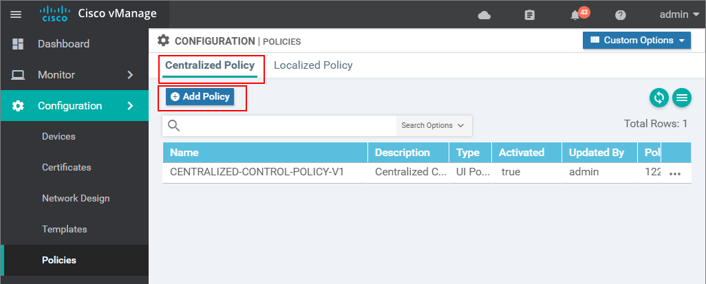
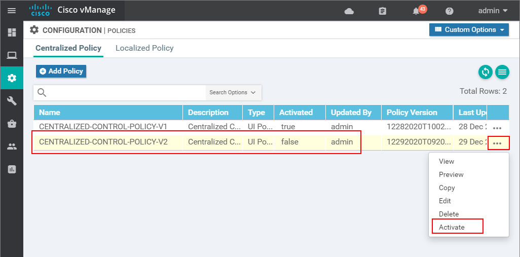
If we log into vManage and enter the Policy Wizard in Configuration > Policies, we can see the Centralized Policy we have created in the last lesson - "CENTRALIZED-CONTROL-POLICY-V1".
IMPORTANT: Centralized Policies cannot be edited while they are active. If we want to modify something, we create a new centralized policy and activate it.
Therefore, we should create another policy - "CENTRALIZED-CONTROL-POLICY-V2" reusing the same parts of the previous one, and push it to the vSmart controller. You can now see why it is a good practice to have a version number in the name.
To reuse existing parts of a centralized policy, we make a copy of them and modify the copy. Let's see this in action, go to the Custom Options drop-down menu and select Topology as shown in step 1.
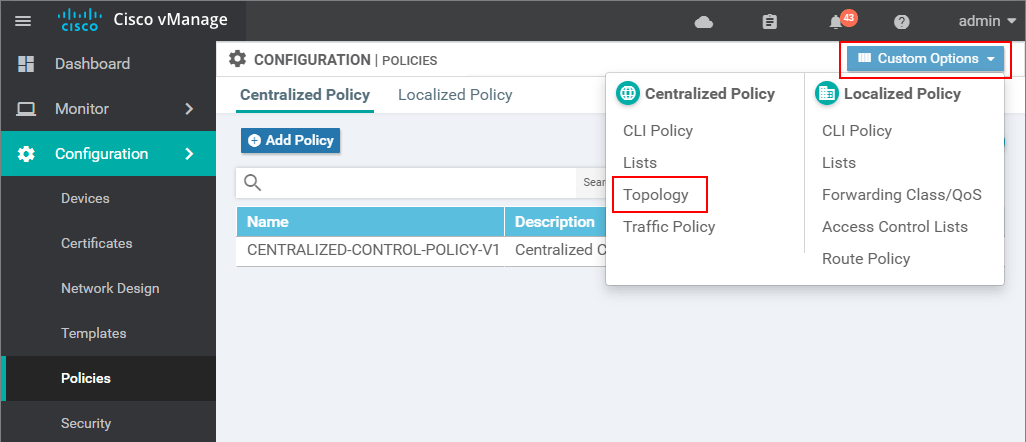
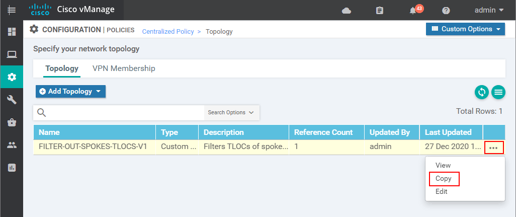
There you will see the Topology policy we have created in the last lesson. To reuse it, we make a copy of it with another name and description.
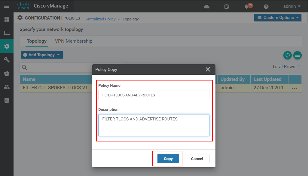
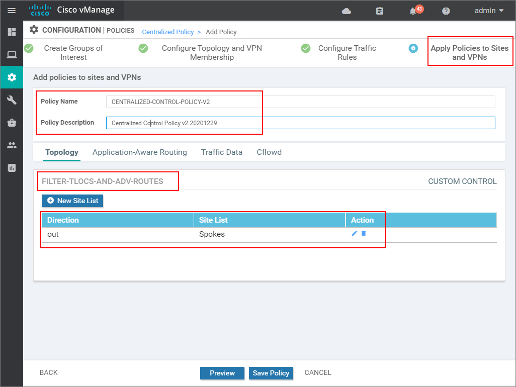
The first thing that must be specified in order to make a copy is the name and description. For this example, we are going to use "FILTER-TLOCS-AND-ADV-ROUTES".
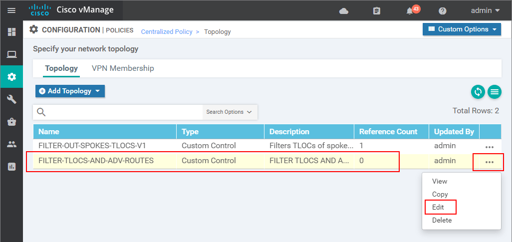
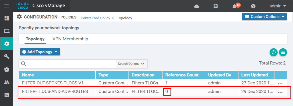
Now you can see that we have two topology definitions. The newly created one has a Reference Count of 0, which means that it is not used anywhere, so we can safely edit it without affecting anything in production.
This leads us to the Centralized Policy > Topology > Edit Custom Control Policy page. There you will find the TLOC sequence we have created in the previous lesson because we use a copy of the last lesson's policy. Now we want to add another match-action sequence, but this time of type Route because we want to manipulate the route advertisements. Click on Sequence Type > Route.
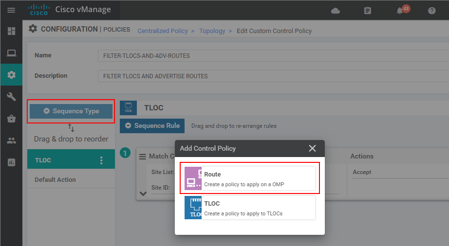
Then we add a new Sequence Rule that matches a prefix-list ALL-ROUTES. This is a pre-defined prefix-list that matches all routes - 0.0.0.0/0 le 32.
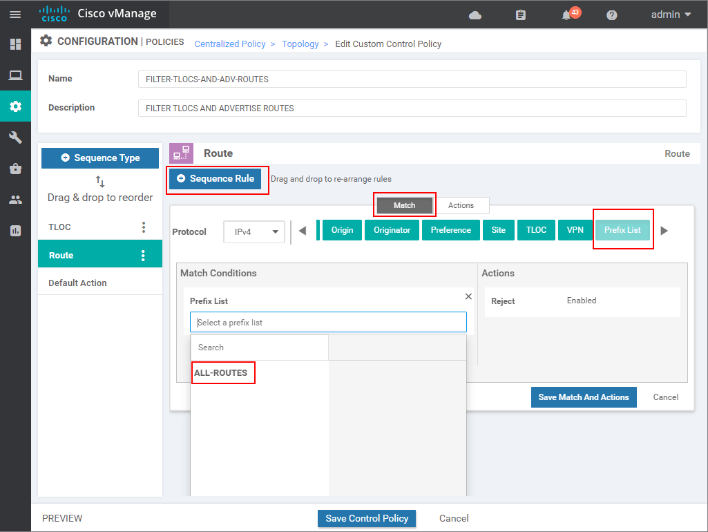
Then we go to the Actions tab and specify Accept action. In the end, we should have the following match-action condition. Then we click save.
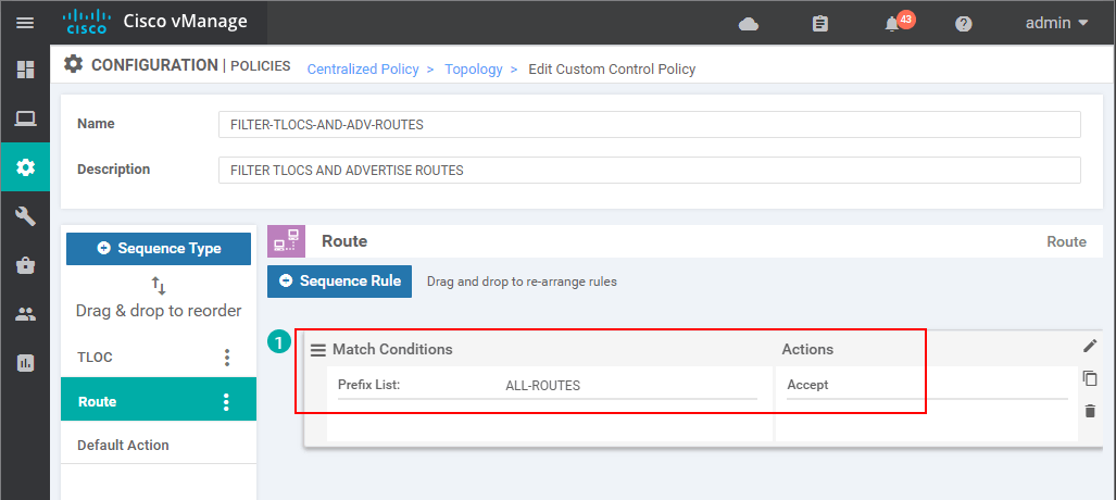
At this point, we have created a new topology match-action definition. However, based on the Reference Count = 0, you can see that it is still not used anywhere. We are going to create
Then we go back to the Policy Wizard in Configuration > Policies and click Add Policy.
We skip the first Create Groups of Interest page because we do not need any new lists. On the Configure Topology and VPN Membership page, we go to Add Topology, but this time we select Import Existing Topology.
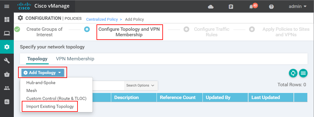
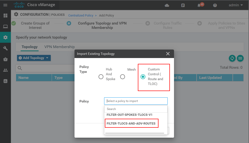
There under the Custom Control (Route and TLOC) radio button, we should see the new custom topology policy and we have just created - "FILTER-TLOCS-AND-ADV-ROUTES".
Then we skip the Configure Traffic and Rules page and end up on the Apply Policies to Sites and VPNs. There we apply the policy in an outbound direction to the spokes using the Spokeslists we have created in the last lesson.
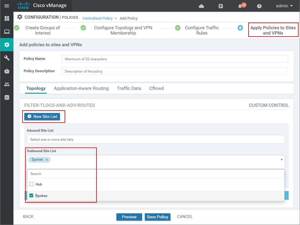
In the end, we specify the name and description, verify that the Direction and Site list are correct, and click Save.
Now you can see that we have two Centralized Policies. You can see that the one we have created in the last lesson has the Activated tab value as true, which means that it is currently active on the vSmart controllers. Now we need to activate the new one that we have made in this lab as shown in the following screenshot.
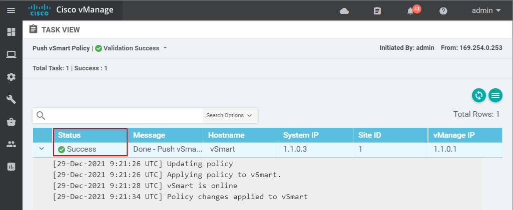
If the vSmart controller is online and is in vManaged mode, the policy should get pushed successfully.
Now the new one which has V2 in the name must have the Activated value true. You can now see why having some kind of version control in the name is really important. You can keep track of the configuration changes and can easily roll back to a previous version in case of a problem.
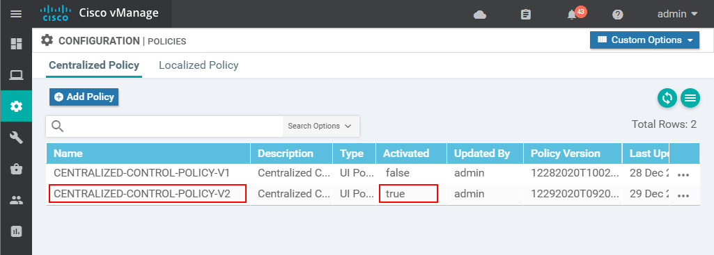
Figure 3 visualizes what we have done in this lab using the Policy Wizard. We have created a policy named CENTRALIZED-CONTROL-POLICY-V2 that holds everything together. There we use the two lists HUB and SPOKES that we had specified in the previous lesson. We have created Custom Topology definition called FILTER-TLOCS-AND-ADV-ROUTES. Inside it, sequence 1 of type tloc matches and accepts tlocs from the hub site. Sequence 11 of type route, matches and accepts all routes. Then, in the end, we have the default reject-action. At first, for most network engineers that are used to starting at CLI outputs, this is more clear and easy to understand than the vManage GUI. In the end, we apply this topology definition in an outbound direction to the spokes.

Now let's check again whether the spoke sites receive any routing information via OMP and if there is any IP reachability.
vEdge-4# sh ip route vpn 1

                                  NEXTHOP
VPN PREFIX           PROTOCOL     IF NAME     TLOC IP        COLOR            ENCAP
-----------------------------------------------------------------------------------
1   172.16.50.0/24   omp          -           50.50.50.50    mpls             ipsec
1   172.16.50.0/24   omp          -           50.50.50.50    public-internet  ipsec
1   172.16.50.0/24   omp          -           50.50.50.51    mpls             ipsec
1   172.16.50.0/24   omp          -           50.50.50.51    public-internet  ipsec
1   172.16.70.0/24   connected    ge0/2       -              -                -
From the above output, you can see that vEdge-4 gets the hub local-network 172.16.50.0/24 via OMP. It now knows that this subnet is reachable over four different overlay tunnels. Pinging to the hub is also successful. However, the spokes' local networks are not present in the routing table of vEdge-4 and there is no spoke-to-spoke reachability. But wait, we have configured a centralized policy that enables all routes to be advertised to the spoke sites, why they are still not present at vEdge-4?
vEdge-4# ping vpn 1 172.16.50.1 --> (the hub site-id 50)
Ping in VPN 1
PING 172.16.50.1 (172.16.50.1) 56(84) bytes of data.
64 bytes from 172.16.50.1: icmp_seq=1 ttl=64 time=48.2 ms
64 bytes from 172.16.50.1: icmp_seq=2 ttl=64 time=35.7 ms
64 bytes from 172.16.50.1: icmp_seq=3 ttl=64 time=57.5 ms
^C
--- 172.16.50.1 ping statistics ---
3 packets transmitted, 3 received, 0% packet loss, time 2003ms
rtt min/avg/max/mdev = 35.742/47.196/57.549/8.936 ms

vEdge-4# ping vpn 1 172.16.80.1 --> (a spoke with site-id 80)
Ping in VPN 1
PING 172.16.80.1 (172.16.80.1) 56(84) bytes of data.
From 127.1.0.2 icmp_seq=1 Destination Net Unreachable
From 127.1.0.2 icmp_seq=2 Destination Net Unreachable
From 127.1.0.2 icmp_seq=3 Destination Net Unreachable
^C
--- 172.16.80.1 ping statistics ---
3 packets transmitted, 0 received, +3 errors, 100% packet loss, time 1999ms
Actually, vEdge-4 receives all routes from the vSmart controller as we have specified in the centralized policy. The problem is that in order to install a route in the routing table, vEdge-4 must be able to resolve the TLOC IP of the route. If we take the local network 172.16.60.0/24 of site 60 for example, the TLOC IP of the route entry would be (60.60.60.60, lte, ipsec). However, if we check whether vEdge-4 knows about this TLOC, it is obviously not present in the known tloc-paths.
vEdge-4# show omp tloc-paths
tloc-paths entries 50.50.50.50 mpls ipsec
tloc-paths entries 50.50.50.50 public-internet ipsec
tloc-paths entries 50.50.50.51 mpls ipsec
tloc-paths entries 50.50.50.51 public-internet ipsec
tloc-paths entries 70.70.70.70 mpls ipsec
tloc-paths entries 70.70.70.70 public-internet ipsec
Therefore, the route entry for 172.16.60.0/24 could not be installed in the routing table. This can be easily verified with the show omp routes command ob vEdge-4. You can see in the output below that the wan edge route really really has received the route but it has status flags - Inv and U. Inv means invalid and U means unresolved because the TLOC IP of the route is not known.
vEdge-4#show omp routes 172.16.60.0/24 detail
---------------------------------------------------
omp route entries for vpn 1 route 172.16.60.0/24
---------------------------------------------------
            RECEIVED FROM:
peer            1.1.0.3
path-id         5
label           1
status          Inv,U
loss-reason     not set
lost-to-peer    not set
lost-to-path-id not set
    Attributes:
     originator       60.60.60.60
     type             installed
     tloc             60.60.60.60, lte, ipsec
     ultimate-tloc    not set
     domain-id        not set
     overlay-id        1
     site-id          60
     preference       not set
     tag              not set
     origin-proto     connected
     origin-metric    0
     as-path          not set
     unknown-attr-len not set
You can see that the vSmart controller in a way acts as a BGP route reflector. It reflects the omp routes but does not change the next-hop TLOC addresses. In a full mesh overlay topology, this is the desired behavior, but in the case of a custom topology as the hub-and-spoke overlay we have created, this breaks the data plane.
There are two ways to resolve this problem and enable spoke-to-spoke communication through the hub:
- Using summarization - The simplest way to enable branch-to-branch communication is to inject a default route into the overlay from the hub's vEdges. This is the technique we are going to use in this lesson.
- Using TLOC lists - The 'software-defined' approach to fix the data plane would be to edit our Centralized Policy in such a way that the vSmart controller advertises all spokes' routes with "next-hop" TLOC addresses the TLOCs of the hub's vEdges. This is what we are going to do in the next lab lesson in this series.
Injecting a default route is a pretty simple and straightforward process. We need to create a static route to 0.0.0.0/0 to null0 and just tell the omp protocol that we want to redistribute static routes.
vEdge-1(config)# vpn 1
vEdge-1(config-vpn-1)# ip route 0.0.0.0/0 null0
vEdge-1(config-vpn-1)# omp
vEdge-1(config-omp)# advertise static
vEdge-1(config-omp)# commit
Commit complete.
vEdge-1#
Once the above commands are committed we can see the all spoke edge routers receive a default via each overlay tunnel.
vEdge-4# show ip routes vpn 1 0.0.0.0/0
Codes Status flags:
  F -> fib, S -> selected

VPN    PREFIX       PROTOCOL TLOC IP        COLOR            ENCAP  STATUS
----------------------------------------------------------------------------
1      0.0.0.0/0    omp      50.50.50.50    mpls             ipsec  F,S
1      0.0.0.0/0    omp      50.50.50.50    public-internet  ipsec  F,S
1      0.0.0.0/0    omp      50.50.50.51    mpls             ipsec  F,S
1      0.0.0.0/0    omp      50.50.50.51    public-internet  ipsec  F,S
You can now see that there is spoke-to-spoke reachability and based on the traceroute output, the traffic path is obviously going through the hub.
vEdge-4# ping vpn 1 172.16.60.1
Ping in VPN 1
PING 172.16.60.1 (172.16.60.1) 56(84) bytes of data.
64 bytes from 172.16.60.1: icmp_seq=1 ttl=63 time=92.9 ms
64 bytes from 172.16.60.1: icmp_seq=2 ttl=63 time=68.9 ms
64 bytes from 172.16.60.1: icmp_seq=3 ttl=63 time=71.9 ms
^C
--- 172.16.60.1 ping statistics ---
3 packets transmitted, 3 received, 0% packet loss, time 2002ms
rtt min/avg/max/mdev = 68.995/77.967/92.909/10.636 ms

vEdge-4# traceroute vpn 1 172.16.60.1
Traceroute  172.16.60.1 in VPN 1
traceroute to 172.16.60.1 (172.16.60.1), 30 hops max, 60 byte packets
 1  172.16.50.2 (172.16.50.2)  29.548 ms  29.632 ms  29.616 ms
 2  172.16.60.1 (172.16.60.1)  71.594 ms  71.614 ms  71.621 ms