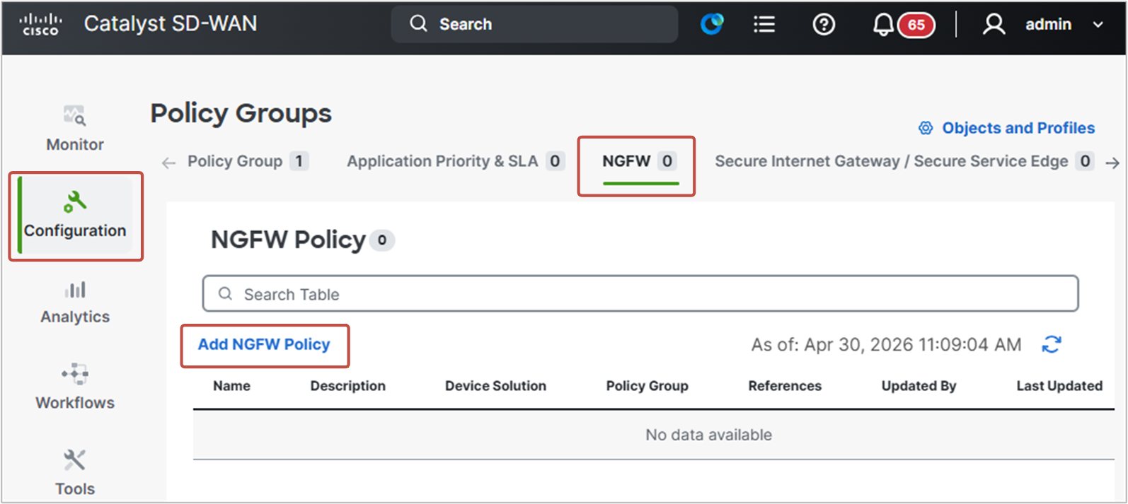
Continuing our security policy, we need to create a new NGFW policy next (notice that prior to version 20.15, NGFW was called Embedded Security). We go to Configuration > Policy Groups > NGFW and select Add NGFW Policy, as shown in the screenshot below.
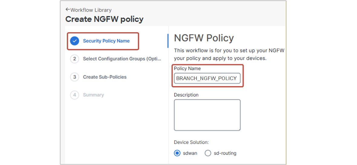
The NGFW policy workflow opens. In the first step, we specify the policy name and device solution “sdwan”, as shown in the screenshot below.
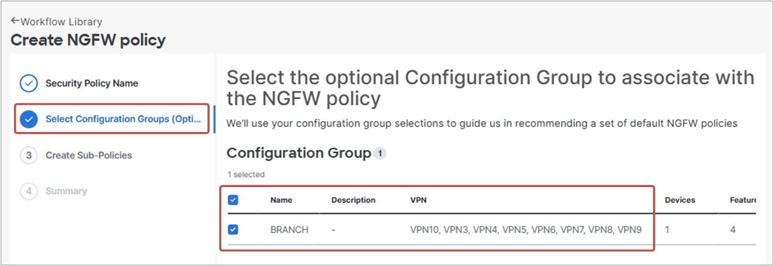
Next, we select the configuration group assigned to the target devices. This step is important because the NGFW policy uses the configuration group to discover which VPNs and interfaces are available on the target routers. Based on this information, the workflow can build the correct zones and zone pairs. For example, based on the configuration group associated with cEdge-3, the NGFW policy knows that VPNs 3-10 and interfaces Gig 1- Gig 10 are available on the routers associated with this configuration group.
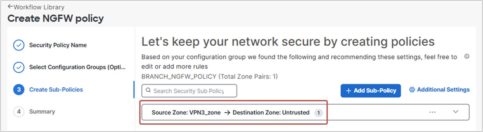
When we click Next, the workflow reads the VPNs available from the configuration group applied to cEdge-3. It then suggests DIA zone pairs for each VPN, such as VPN3->Untrusted. The Untrusted zone represents VPN 0, which is used for Direct Internet Access (DIA).
Basically, the workflow assumes that each service VPN may need controlled access to the Internet through DIA. Therefore, it suggests a zone pair between each VPN and the Untrusted zone. Since the default action of the policy is Drop, any Internet-bound traffic that is not explicitly allowed by a firewall rule is dropped (zero trust model).
For this hands-on lab, we do not need all the suggested zone pairs. We can delete the unnecessary ones and keep only the VPN3-to-Untrusted zone pair, as shown in the screenshot below.
Finally, we reach the summary page and click Create NGFW Policy.
Initial State
Before we start adding firewall rules, let’s test the connectivity right now. This gives us a baseline, so we can later run the tests again and clearly see what the applied firewall policy has changed.
The following diagram shows the portion of the lab topology we will use in this hands-on example. Notice that the FQDN database.networkacademy.io resolves to R13’s loopback. For DNS addresses, on R33 we use R13’s Lo0 (10.1.33.1) and a static host entry per FQDN.
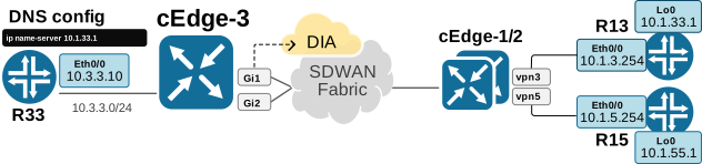
Now let’s run some basic tests. You can see that DNS is working and R33 can ping and telnet to R13’s loopback using the FQDN name.
R33# ping database.networkacademy.io
Type escape sequence to abort
Sending 5, 100-byte ICMP Echos to 10.1.33.1, timeout is 2 seconds:
!!!!!
Success rate is 100 percent (5/5), round-trip min/avg/max = 1/2/6 ms
R33# telnet database.networkacademy.io
Trying database.networkacademy.io (10.1.33.1)... OpenWe can also see that R33 (VPN 3) can telnet R15 (VPN 5) because there is IP reachability between VPN3 and VPN5 since we configured route leaking in lab#7.7.
R33# telnet 10.1.5.254
Trying 10.1.5.254 ... Open
R33 also has access to the Internet via local Direct Internet Access (DIA), as shown below.
R33# ping linkedin.com
Type escape sequence to abort
Sending 5, 100-byte ICMP Echos to 150.171.22.12, timeout is 2 seconds:
!!!!!
Success rate is 100 percent (5/5), round-trip min/avg/max = 1/2/4 ms
Step 2.a. Intra-zone Firewall Policy (VPN3-VPN3)
Let’s first think a bit before we start creating policies. Spend some time thinking about why we need an intra-zone firewall. What would be a common scenario in your organization?
By default, a VPN provides full any-to-any connectivity - every node can freely reach every other, with nothing filtered. That's fine until it isn't. Once a VPN contains critical servers or other sensitive infrastructure, open access from everywhere becomes a liability.
For example, POS system is in the DC in VPN3. All POS terminals are at branches in VPN3. You don’t want to allow unrestricted access from terminals to the centralized POS. Someone can unplug a terminal, connect a rogue device, and try exploiting vulnerabilities by probing open ports.
This is where an intra-zone firewall policy becomes useful. It allows you to apply security controls at branches to traffic that stays inside the same VPN, enforcing tighter access controls between internal devices without leaving everything wide open.
Now, let’s go back to the hands-on example and start with the Intra-zone Firewall part that has the following requirements:
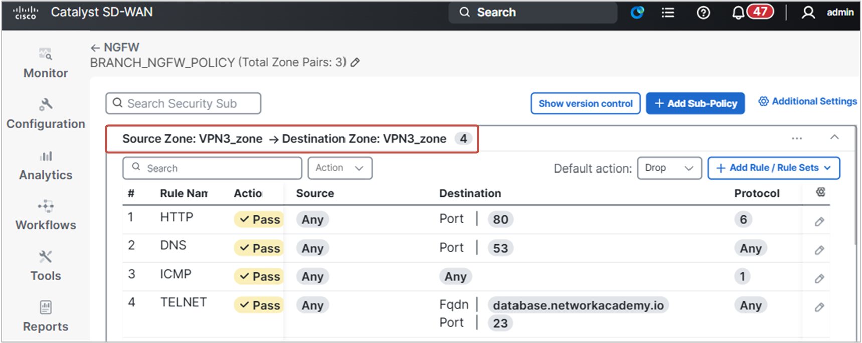
- Within VPN 3, only DNS, HTTP, and ICMP should be allowed. This traffic must be passed transparently in both directions, without connection-state tracking.
- TELNET access must be allowed to the server database.networkacademy.io irrespective of the IP address of the host.
When we first go and edit the NGFW policy we have just added, we see only one zone pair, VPN3-Untrusted, that was automatically created, as shown in the screenshot below.
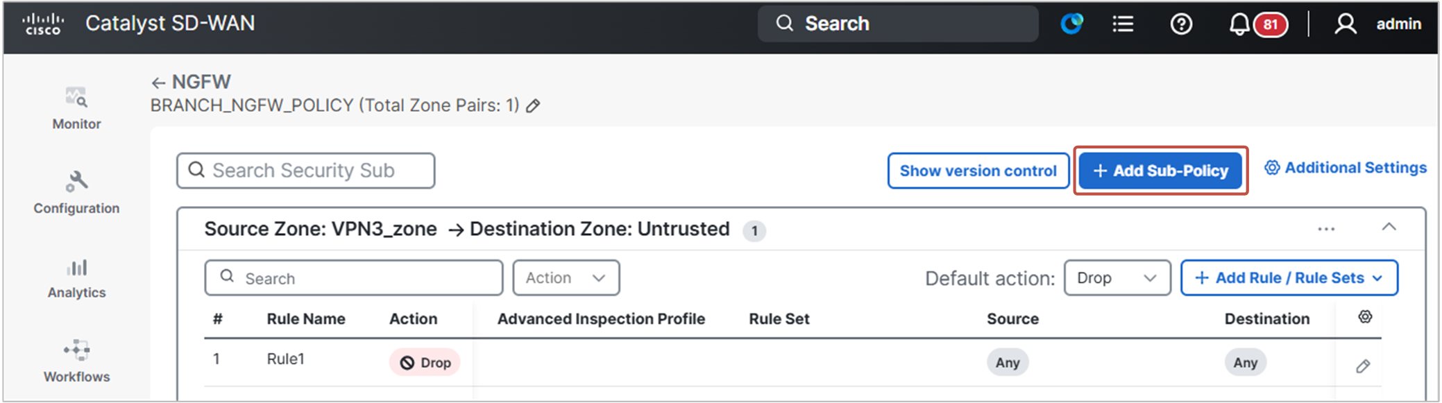
However, for the Intra-zone firewall policy, we need to create another zone pair, VPN3-VPN3. We go to Configuration > Policy Groups > NGFW and edit the BRANCH_NGFW policy.
Then we click on the +Add Sub-Policy button. A new window slides from the right, and we create a VPN3-VPN3 zone pair.
Next, we open the new zone pair and click the + Add Rule / Rule Sets button on the right.
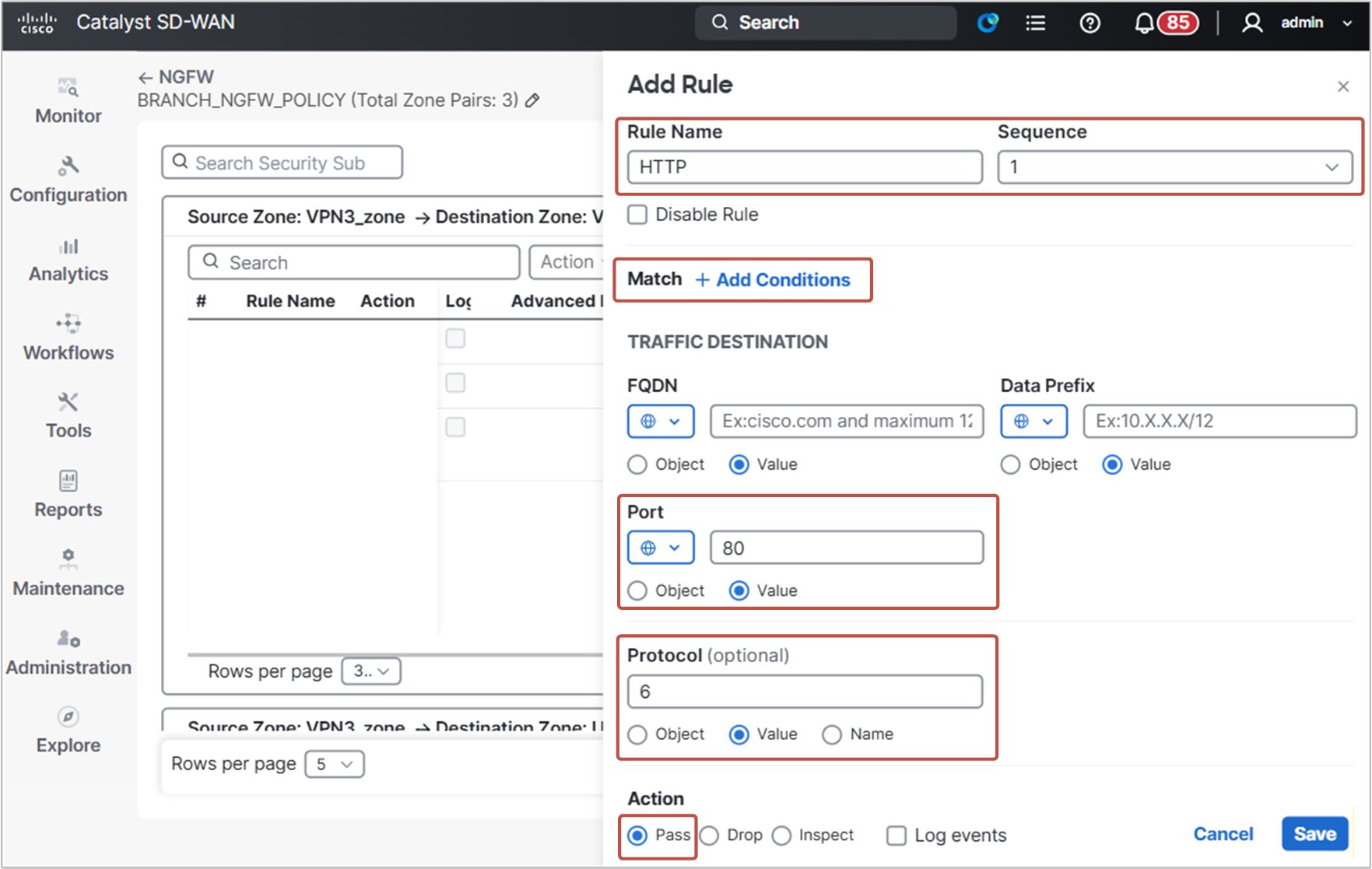
Next, we add the rules that satisfy the lab requirements, as shown in the screenshot above. Notice the Match + Add Conditions button. When you click it, you can add or remove different match conditions such as source and destination prefix/port, FQDN, Application, and so on. In the end, you should have rules similar to the ones in the screenshot below.
Step 2.b. Inter-zone Firewall Policy (VPN3-VPN5)
Let’s spend some time thinking again - why do we need an inter-zone firewall policy? This time it is a bit different. VPNs provide isolation at Layer 3 - by default, there is no connectivity between VPN segments. Nodes in VPN3 cannot reach nodes in VPN5, and that's by design.
In practice, however, almost every SD-WAN deployment ends up with some route leaking between VPNs. Some services need to be shared - management servers, syslog, telemetry collectors, NTP, printers, shared storage, etc. To demonstrate that, in lab#7.7, we leaked VPN3's 10.3.3.0/24 into VPN5, and VPN5's 10.1.5.0/24 into VPN3.
But when you introduce reachability between VPNs, it becomes even more important to restrict access to exactly the services that need to be shared and nothing more. Wide-open connectivity between VPNs undermines the purpose of having them separate in the first place. If nodes in VPN3 can freely reach anything in VPN5, why are they in different VPNs at all?
Inter-zone firewall policy is how you preserve the intent of VPN isolation while still allowing the controlled, service-specific exceptions that the business requires. It is strongly recommended to use a firewall policy when you do route leaking at the VPN level.
Now, let's go back to the hands-on example. We move on to the Inter-zone requirements:
- Only HTTPS and ICMP must be allowed from VPN3-10.3.3.0/24 to VPN5-10.1.5.0/24.
- Connections should only be initiated from VPN3 to VPN5.
Adding the firewall rules that satisfy these requirements is pretty straightforward. The following screenshot shows how we did it.
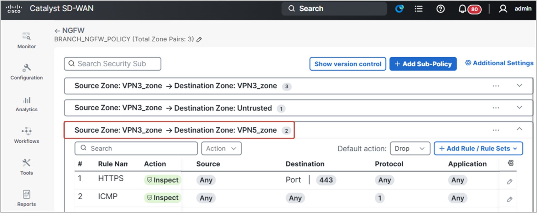
Notice that we only need a zone pair in the direction VPN3->VPN5. The Inspect action is stateful; it tracks active connections and allows return traffic automatically, so a reverse zone-pair for return traffic is not required.
Step 2.c. DIA Firewall Policy (VPN3-VPN0)
Let’s begin with the same question again - why do we need a DIA firewall policy? This one is easy, though. If you provide Direct Internet Access at branches and don’t apply security, you basically open the branches to the entirety of the Internet. This exposes the organization to serious cybersecurity risks, such as:
- Unauthorized access to web and storage resources.
- Leakage or theft of sensitive customer or corporate data.
- Phishing and spear-phishing attacks.
- Malware, including viruses, spyware, and Trojans.
- Ransomware attacks.
The impact is not limited to IT. A security incident can damage the organization’s reputation and even create legal or regulatory problems. For these reasons, any organization enabling local DIA at branches is strongly advised to deploy security features, such as DIA Firewall policy, URLF, AMP, IPS, and TLS/SSL Proxy, as well.
Now, let’s go back to our hands-on example and look at the DIA requirements listed below:
- Only SSH, DNS, NTP, HTTP, HTTPS, and ICMP should be allowed from VPN3 to the Internet (0.0.0.0/0).
- Connections should only be initiated from VPN3 to the Internet.
Notice that this time, we have a requirement to allow six different services to the Internet. In a real-world scenario, this could be a requirement to allow 100+ services. You cannot build a separate rule for every service. It is just not scalable and would be a nightmare to maintain.
Pay attention to the fact that the NGFW rules can match traffic by using direct values, as we have done so far. However, rules do not have to use only direct values. They can also use objects. Engineers with prior firewall experience know that an object is a reusable definition that represents one or more values. For example, an object can contain a group of ports.
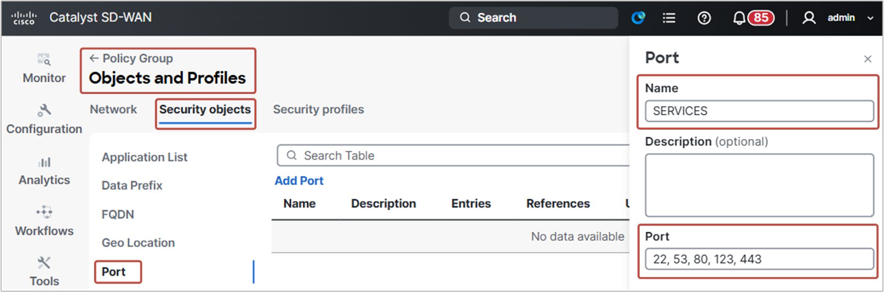
Let’s create a new object that represents the destination ports that we need to allow in this DIA firewall policy. We go to Configuration > Policy Groups > Objects and Profiles > Security Objects > Port and then specify the ports, as shown in the following screenshot.
Now, go ahead and create firewall rules that satisfy the lab requirement for direct internet access. Go to Configuration > Policy Groups > NGFW and edit the BRANCH_NGFW_POLICY. Then add the following firewall rules:
- At sequence 1, rule named “ALLOWED_SERVICES” that matches the destination port object “SERVICES” that we have just created. Then specify action Inspect.
- At sequence 2, rule named ICMP matches protocol number 1 and specifies action Inspect, as shown in the following screenshot.
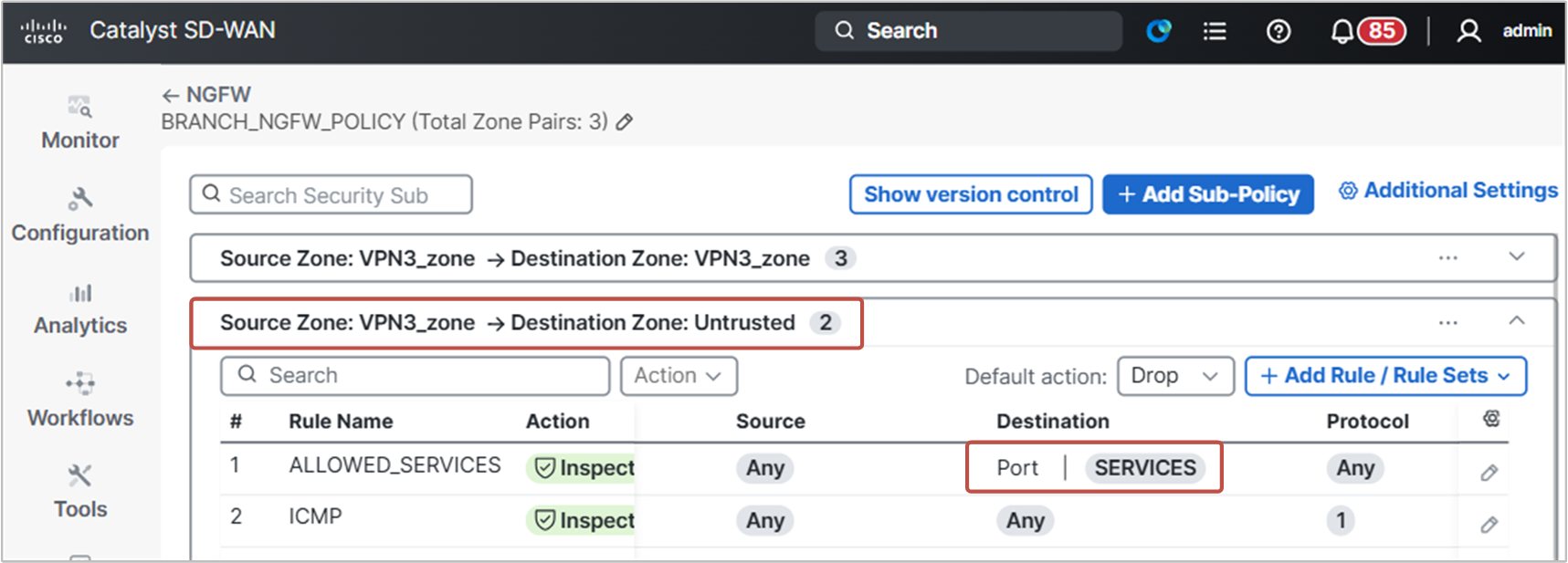
For engineers who are new to firewalls, it may not seem important whether you enter the ports directly in the rule or place them in an object. After all, you still have to define the ports somewhere. However, there is an essential difference.
Objects make firewall policies much easier to scale and maintain. Instead of creating separate rules for SSH, DNS, NTP, HTTP, and HTTPS, you can create one object that contains all required ports. Then you refer to that object in the firewall rule, as we did in this example.
Later, if the requirement changes and you also need to allow SIP, for example, you can update the object once. Every rule that uses that object automatically follows the new definition.
Remember that scaling is all about reusability. Objects are the tool that allows you to reuse traffic definitions across rules. They are a very important scaling tool in firewall rules design, especially in large-scale deployments with hundreds/thousands of rules.
Step 2.d. Create and apply Policy Group
At this point, we created the firewall policy that we needed to satisfy the requirements. However, the policy is not applied anywhere and is not in effect. To apply the NGFW policy to the branch, we need to create a new Policy Group and include it there.
A Policy Group is a reusable container that defines which data, app-route, and security policies are applied to a group of edge routers. More on policy groups in Volume 2.
We go to Configuration > Policy Groups and select the Add Policy Group button. Then you create a new policy group named “BRANCH_POLICY”.
In the NGFW dropdown field, we select the BRANCH_NGFW_POLICY that we have just created and click the Save button.
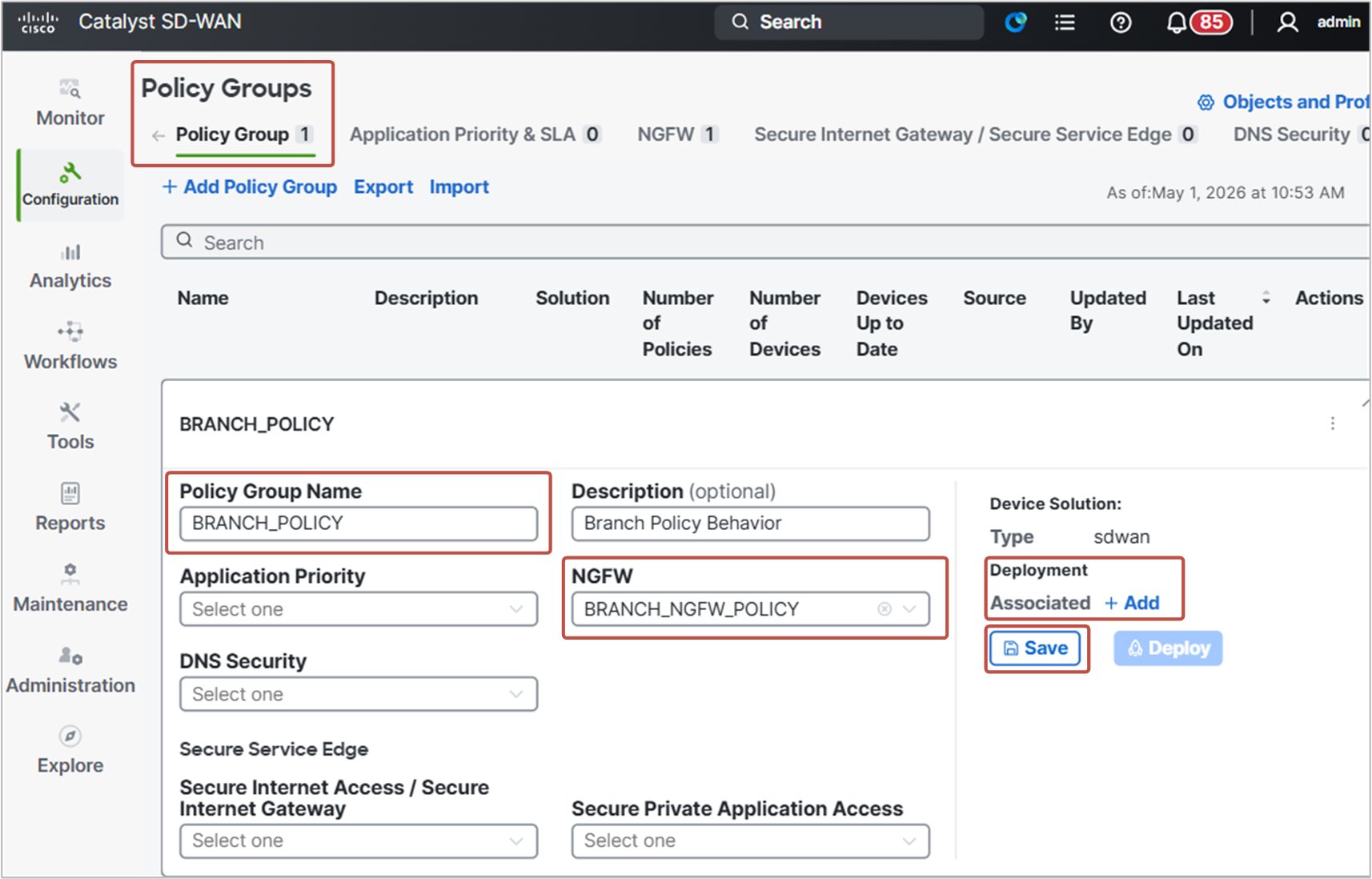
Then we go to the Associated +Add button on the right to associate cEdge-3 with this policy group. A new window slides from the right. You click the Associate Devices button.
In the Device Associate workflow, we select SITE-3, cEdge-3, and click Next. The workflow asks whether we want to provision the device. We select Yes and enter the provisioning page. Then we simply select cEdge-3 and click Next, Next, Finish, and wait for the policy group to be deployed.
Step 2.e. Verify the Intra-zone Firewall Policy
Recall that a firewall policy is unidirectional and is applied to a zone pair. Therefore, the first verification step is to check whether your zones are correct and paired correctly. Remember the following facts:
- The traffic direction is from the source to the destination zone. Therefore, inter-zone policies (VPN3->VPN5) are unidirectional, and intra-zone policies (VPN3 -> VPN3) are practically bi-directional.
- There are three firewall actions that we can apply to traffic:
- Inspect –a firewall session is created in the connection table for the matched traffic. The return traffic is inspected and permitted automatically.
- Pass – the packet is allowed to pass without further inspection. The return traffic is not allowed by default. Another firewall policy applied to another zone-pair must allow the return traffic; otherwise, it is dropped. In the case of an intra-zone policy, traffic is passed in both directions because both directions match the VPN3->VPN3 policy.
- Drop – the packet is explicitly dropped.
- By default, the firewall policy drops traffic flows that are not explicitly allowed by a rule.
Now, let’s run the initial tests from step 2 again and see whether the results are different.
R33# ping database.networkacademy.io
% Unrecognized host or address, or protocol not running.
R33# telnet database.networkacademy.io
% Bad IP address or host nameR33# telnet 10.1.33.1
Trying 10.1.33.1 ...
% Connection timed out; remote host not respondingR33# ping 10.1.33.1
Type escape sequence to abort.
Sending 5, 100-byte ICMP Echos to 10.1.33.1, timeout is 2 seconds:
!!!!!
Success rate is 100 percent (5/5), round-trip min/avg/max = 1/2/6 msObviously, DNS and TELNET don’t work. However, ICMP is working. But why? We allowed DNS and TELNET using the firewall action Pass. Spend a moment thinking about it. What could be the problem? Traffic is allowed with Pass action in both directions, but it obviously doesn’t work.
Let’s begin with the fundamentals. Recall that a zone pair implies direction. A rule in a zone pair from VPN3 to Untrusted, for example, applies to traffic that goes from VPN3 toward VPN0. It does not automatically apply in the opposite direction. However, an intra-zone pair is a special case. If the source and destination zones are the same, such as VPN3 to VPN3, the same policy applies to traffic in both directions because both sides of the flow belong to the same zone.
Recall another important detail - the firewall action Pass is stateless. It allows the matching packets through, but it does not track the connection. Hence, return traffic is not allowed by default. Another firewall policy applied to a different zone pair in the opposite direction must allow return traffic. However, the opposite direction is the same VPN3->VPN3, so the traffic must match the same firewall rule and be allowed, right?
Here, the key point is must match. The following diagram visualizes what is wrong with the firewall rules that we created and why DNS and TELNET don’t work at the moment.
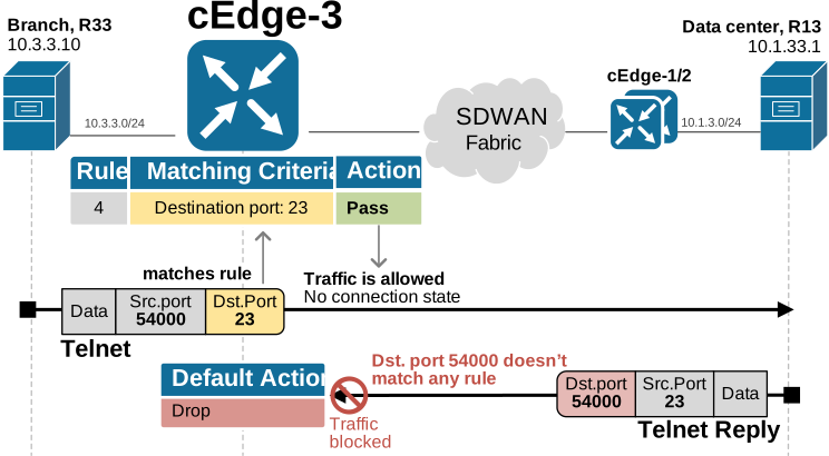
The initial Telnet packet from R33 to R13 has destination port 23, so it matches the rule and is allowed. However, the return traffic is different. In the return direction, port 23 is now the source port, while the destination port is a random port used by the client. Because the return packet no longer has destination port 23, it does not match any rule. As a result, it is dropped by the firewall policy’s default action.
With the Inspect action, this behavior is different. The router tracks the connection state and expects the return traffic, so the return packets are allowed automatically as part of the same session/connection.
Therefore, when you use Pass, you must think at the packet level, not at the session level. Even when the zone pair covers both directions, as in a VPN3-to-VPN3 intra-zone pair, return packets still need to match a rule. If you match by prefix or port, in the opposite direction, return traffic won’t match because the destination address and ports are now different.
There are two solutions to this problem:
- You can change the matching rule to something symmetric that is the same in both directions. This could be a protocol (TCP/UDP/ICMP/etc) or an NBAR2 application.
- You can change the firewall action from Pass to Inspect. Recall that Inspect allows the matched traffic and tracks the connection at the same time. Subsequently, return traffic of already established connections is automatically allowed, as shown below.
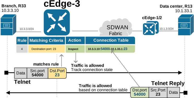
In our case, let’s change the action of rules HTTP, DNS, and TELNET from PASS to INSPECT. Go to Configuration>Policy Groups>NGFW and edit the BRANCH_NGFW_POLICY policy.
Then go to the VPN3_zone->VPN3_zone pair and edit each rule by changing the firewall action. Then click Save. Upon saving, vManage will ask you to provide a comment on what you have just changed. This is required because the NGFW policy has a rollback and versioning feature. It stores 30 versions of the policy, and you can roll back to any previous version with one click. You can also compare any two policy versions to see the differences.
Another important detail is that once you edit and save the NGFW policy, nothing is pushed to edge routers. You must go back to the Policy Group BRANCH_POLICY and redeploy it in order to push the latest version to cEdge-3. You go to Configuration > Policy Group, select the policy, and click Deploy. Then go through the deployment workflow.
Now let’s run the initial tests again and see if telnet to database.networkacademy.io works again.
R33# ping database.networkacademy.io
Type escape sequence to abort.
Sending 5, 100-byte ICMP Echos to 10.1.33.1, timeout is 2 seconds:
!!!!!
Success rate is 100 percent (5/5), round-trip min/avg/max = 1/2/6 ms
R33# telnet database.networkacademy.io
Trying database.networkacademy.io (10.1.33.1)... OpenNow, Telnet and DNS are obviously working because the NGFW policy allows them in the client-server direction, and then the policy allows the traffic in the return direction based on the connection state table.
We can check the firewall’s connection table using the show policy-firewall session command, as shown in the following output.
cEdge-3# show policy-firewall sessions platform
[s=session  i=imprecise channel c=control channel  d=data channel u=utd inspect A/D=appfw action allow/deny]
Session ID:0x00000007 10.3.3.100 54000 10.1.33.1 23 proto 6 (3:2:3:2) (0x46:telnet)
Session ID:0x00000006 10.3.3.100 20312 10.1.33.1 53 proto 17 (3:2:3:2) (0x19:dns)
Another helpful command for monitoring and troubleshooting is show sdwan zonebfwdp sessions
We can also see that the FQDN-based rule is working. Recall that the router’s DNS snooping process must have an entry for database.networkacademy.io. If the router doesn’t have a DNS snooping entry, it won’t be able to enforce the FQDN-based firewall rule.
cEdge-3# show ip dns-snoop all
IP Address Client(s)  Expire    RegexId  VRF ID  Match/
Epoch                                            Name
-------------------------------------------------------------------
10.1.33.1       0x1  8       0xd9a88000 0x0       database\.networkacademy\.io
Now, you can test this rule again by changing the IP address that database.networkacademy.io resolves to from 10.1.33.1 to 10.1.3.254, as shown below.
R13(config)# no ip host database.networkacademy.io 10.1.33.1
R13(config)# ip host database.networkacademy.io 10.1.3.254
Then run tests with ping and telnet to the FQDN. It should continue to work without requiring any update to the firewall rule.